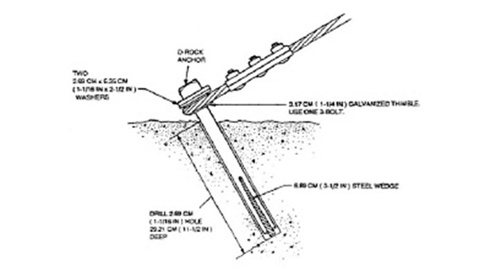
In soils that are harder to penetrate such as com-. Only one guy is to be attached to a rock anchor.

Rock Engineering Design Of Post Tensioned Anchors For Dams A Review Sciencedirect
Type of anchorage anchor head.
. 211 Rock anchors are to be installed and used where solid rock is encountered. Design guide making references to latest technologies appears to be necessary. Tuesday July 06 2004 85935 PM.
Dont over-analyze the shape. Is there a minimum unbonded length required for vertical rock anchors utilized for uplift resistance eg. Condition A - supplementary reinforcement is provided D44 c 3.
Rock anchors rock instrumentation and monitoring. Step 1 Establish project requirements including all geometry external loading conditions temporary and or permanent seismic etc performance criteria and construction. The design strength of the concrete anchoring system is dependent on many factors.
Use 2 tubes for complete grouting. Shallow foundations on rock resisting uplift. The rock anchor is then tensioned to the appropriate level from the exposed end.
Anchor reinft strength is used to replace concrete tension shear. The length of the uplift anchors depends on the required grout to rock bond stress and hole diameter and on the length required for mass stability. According to Eurocode 7 EC7 Part 1 2 the design pull-out resistance of an anchorage R ad must satisfy the following inequality.
This value will be used to deduce the breaking load Ptk t 133 P p and the lock-off load P 0 d 08 P. ReidBar Inserts are developed to provide sufficient embedment to develop the Min. PIP STE05121 Anchor Bolt Design Guide-2006 PIP STE05121 Code Reference Assumptions ACI 318-08 1.
Load combinations shall be as per ACI 318-08 Chapter 9 or ASCE 7-05 Chapter 2 D44 4. Rock Soil Anchors. Page 8 1501 2016.
Typical design steps for retaining walls with ground anchors are as follows. Rock anchors are typically designed with embedments deep enough to ensure ductile failure of the. The reliability of these anchors is extremely important.
Soil anchor in loose soil or rock anchor in rock The anchor load force The anchor capacity is at least defined by the proof load Pp during acceptance testing expressed in kN. The four most critical are. Rock bolt support design takes place in stages.
The grouting tube is affixed to the rod to a point just above the. Choose trial base plate sizes B and N based on geom- etry of column and four-anchor requirements. The rock anchor must be installed at an angle of 45 towards the structure and within 5 of alignment with the guy load.
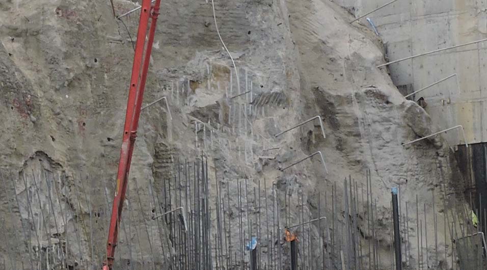
N d 2 3 in B bf 2 3 in 2. One tube pumps grout to the back of the borehole and the other acts as a vent. The compressive stresses resist the anticipated tension stresses induced by the soil movements enhancing the performance over a non-prestressed foundation.
The acquired experience enables TENSACCIAI to. Rock Anchor Design. If the anchors are in a straight row and are not too close together for each anchor you will have a rock mass somewhere between a cone and a pointed straight shaft.
An anchor is a structure consisting of a tendon free length designed to satisfy overall structural stability and a restraint designed to transmit tensile forces to the surrounding ground. Concrete is cracked 2. MAIN FACTORS IN ANCHOR DESIGN 5 CALCULATION OF ANCHOR CAPACITY Calculation can be.
The holding power of rock type anchors is. M N 095d 2 n B - 080bf 2 3. Guide British Tunnelling.
Post-tensioned rock and soil anchors provide a cost-efficient high-performance solution for projects associated with temporary and permanent soil stabilization. Technical Supplement 14E Use and Design of Soil Anchors Figure TS14E3 Post driver being used to install soil anchors Figure TS14E4 Driving soil anchor with a 30-lb jack-hammer anchor can be driven with a sledgehammer or a post-driver in easy-to-penetrate soils fig. This handbook is aimed to set out the design guidelines for post-installed anchor bolt design subject to mainly static loads making references to ETAG 001 Annex C 1 TR029 5 and CENTS 1992-4 2.
If the anchors are close together say in a rectangular grid the mass of rock per each anchor may be a pointed straight shaft equal to the grid spacing. The reduced base section gives rise to tension at the heel of the dam which must then be resisted by rock anchors. Where more than one guy is required separate anchors are to be installed for each guy at a minimum of 2 feet apart and where practical in a direct line with the conductors.
Of geotechnical type of structural type. The compressive strength of the concrete. The depth of the anchor.
Determine plate cantilever dimension m or n in direc- tion of applied moment. Name to the anchor. Tensioned anchors have been used in dam engineering so me aspects of the rock engineering design of high-capacity roc k anchors for dams have changed relatively little o.
In dam design rock anchors have been used to reduce the cross-section of a normal gravity dam with considerable savings in concrete costs. An economical medium strength rod used for tie downs and rock reinforcement. P d R adwhere.
Use AR Expansion cone shell anchor series for blind hole and prestressed rebar anchor applications. Of rock and ground anchors of different types and use in important public and civil works in Italy and all over the world. Rock anchors--design and quality control Author.
Ultimate steel tensile capacity of the bar in 32MPa concrete. The design guidelines can be applied to. B41 Design Procedure for a Small Moment Base 1.
2
Rock Anchor Utility Expanding Rock Anchor Manufacturer Powertelcom
Design Of Rock Anchors Structural Guide

Rock Engineering Design Of Post Tensioned Anchors For Dams A Review Sciencedirect
Determining Anchor Length Williams Form Engineering Corp
Determining Anchor Length Williams Form Engineering Corp

Rock Engineering Design Of Post Tensioned Anchors For Dams A Review Sciencedirect
Spin Lock Rock Anchors Williams Form Engineering Corp
0 comments
Post a Comment